Hi everyone. First and foremost, what a great forum. I tend to spend most of my time lurking and not a lot of time posting. I have built several arcades since my time of joining byoac in 2009 mainly bartops and a few full size cabs. Like most people, I have a busy life and getting time for our hobby is hard at times. For this reason I have tried to streamline my builds by doing things in logical steps and also reducing the amount of cuts / material wastage.
For this reason I have decided to provide you with an account of my bartop construction in the hope that fellow arcaders can learn from my mistakes and make our hobby more enjoyable with what precious hours we have to devote to it. I have made several of these to date, mainly for friends and the odd one or two for fellow arcade nuts.
I hope you enjoy my build. I finished it recently but I am more than open to future suggestions / improvements for my next one.
Im from the UK and for that reason all my measurements will be in mm, my apologies for those that are used to inches.
 The Design
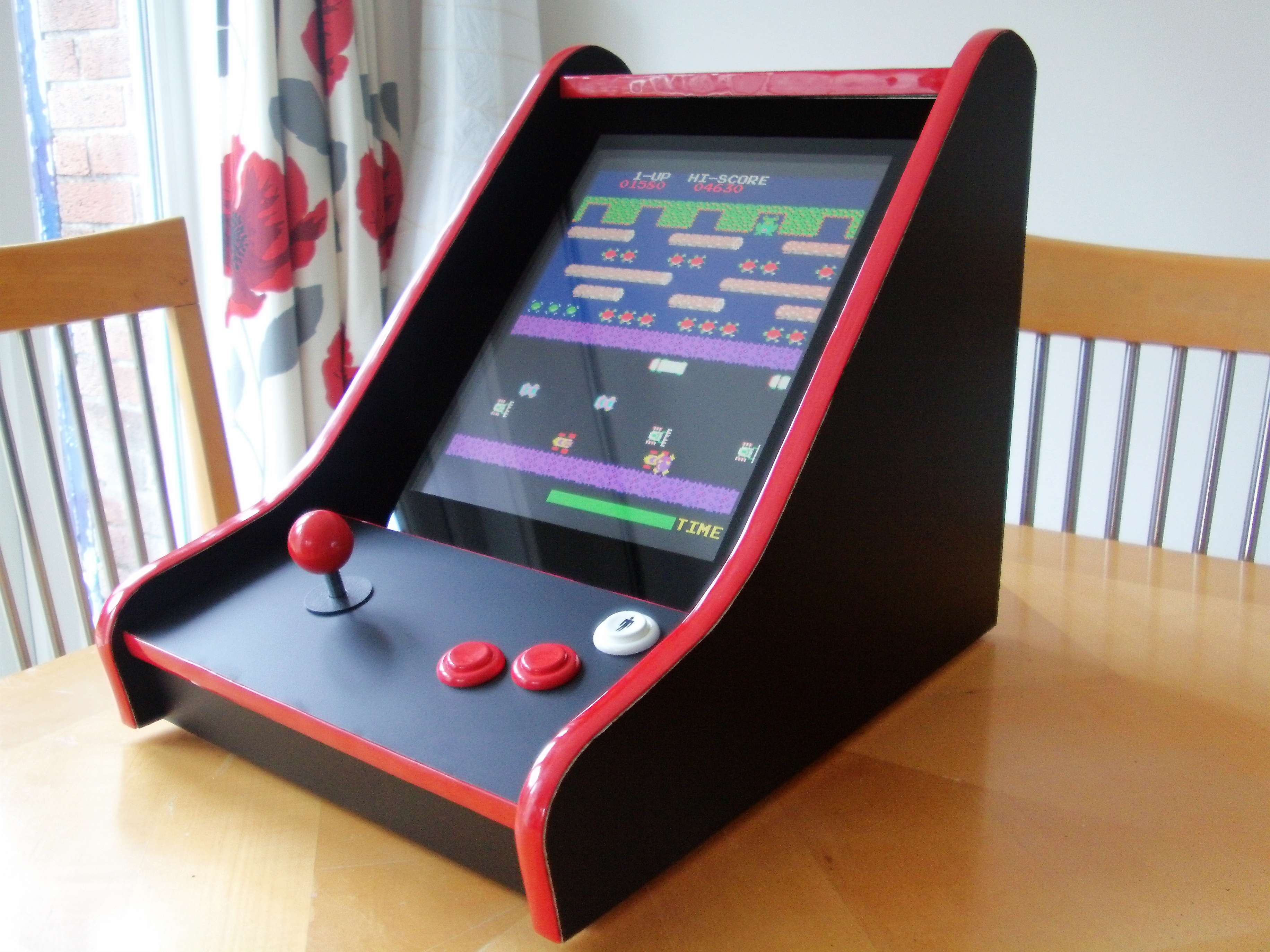
I started out with a basic concept in my head. I wanted the machine to be small, lightish ( how light can you make a lump of wood and metal?) and more importantly efficient with materials. For this reason I chose to negate the marquee and any curved features that would require sanding.
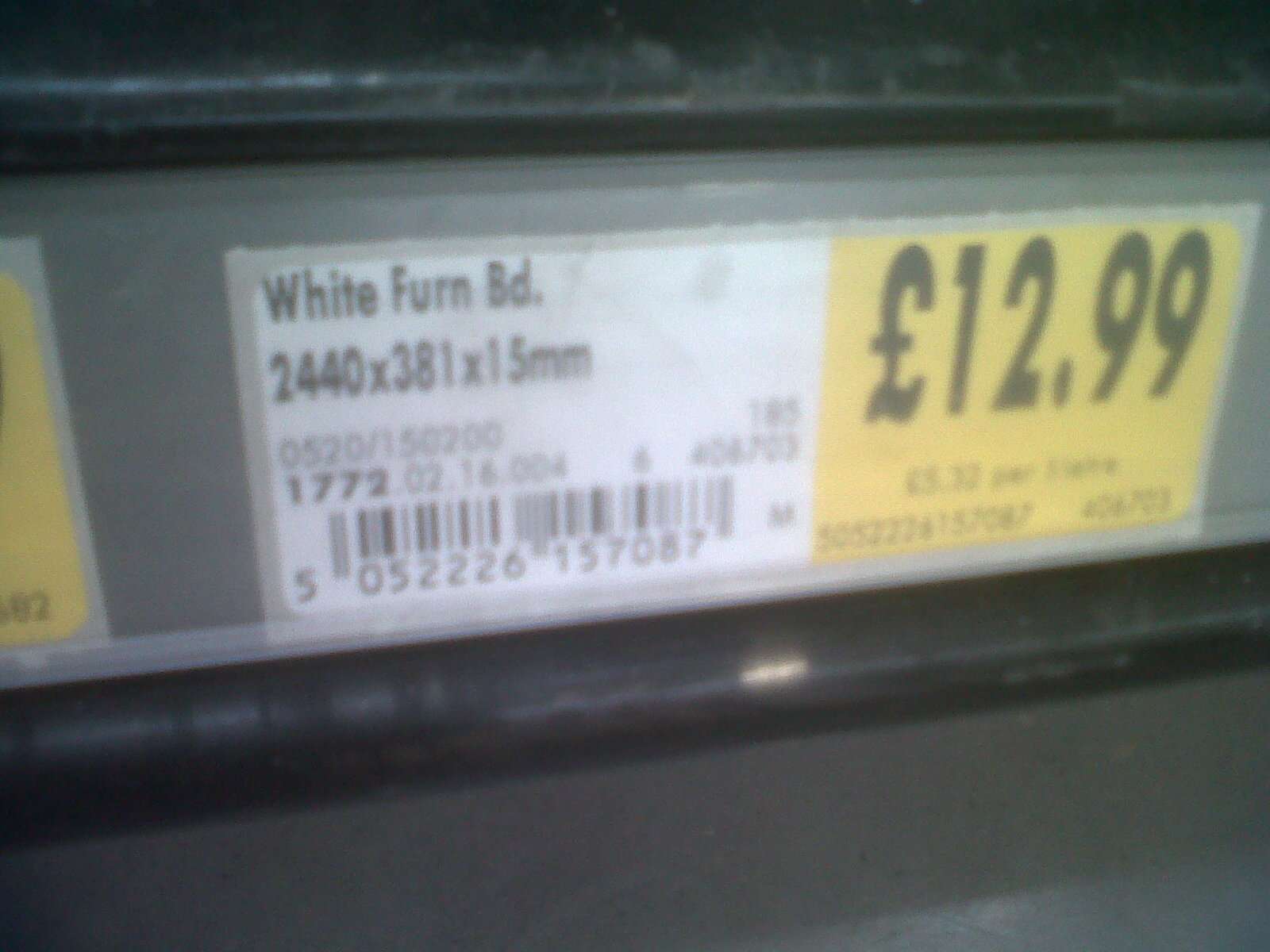
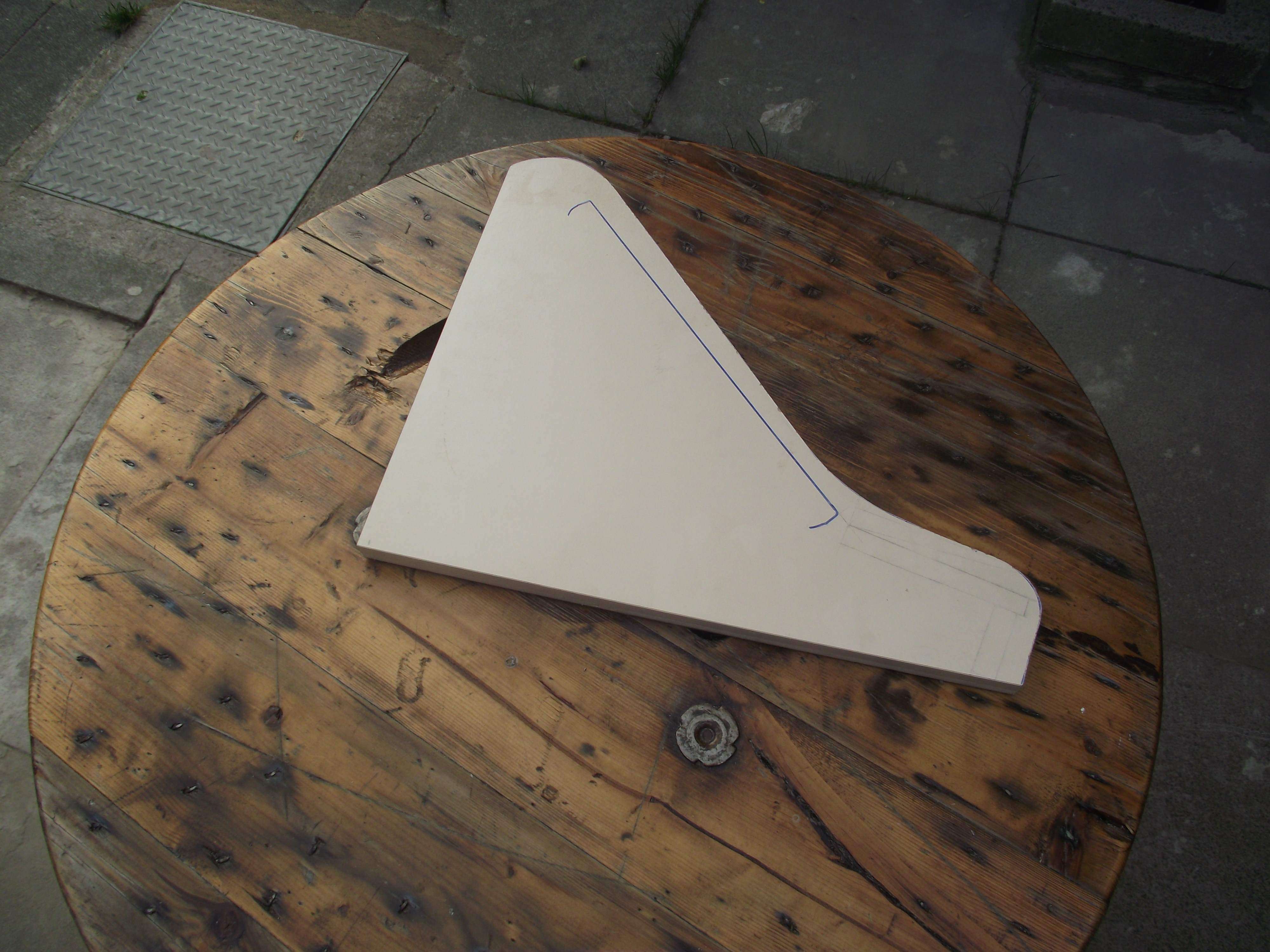
I called into my local diy shop and picked up a sheet of 15mm melamine chipboard.
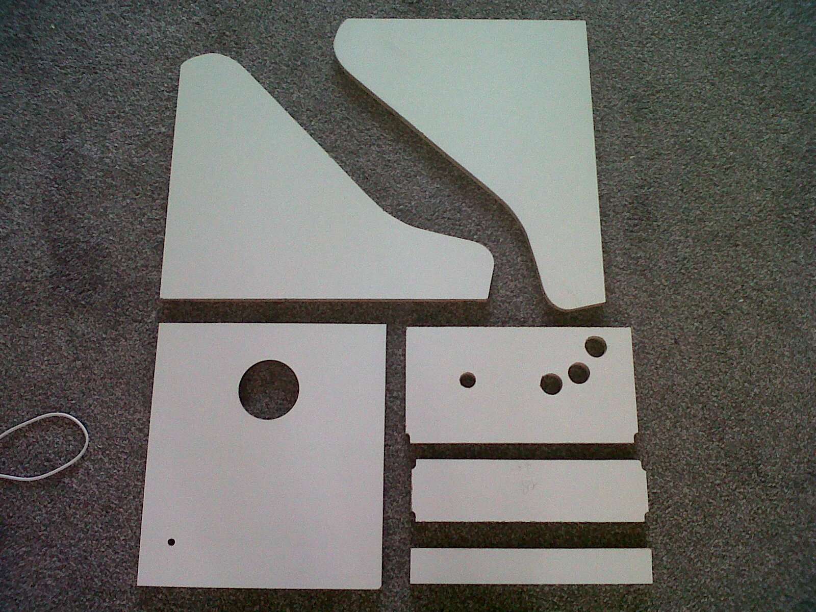
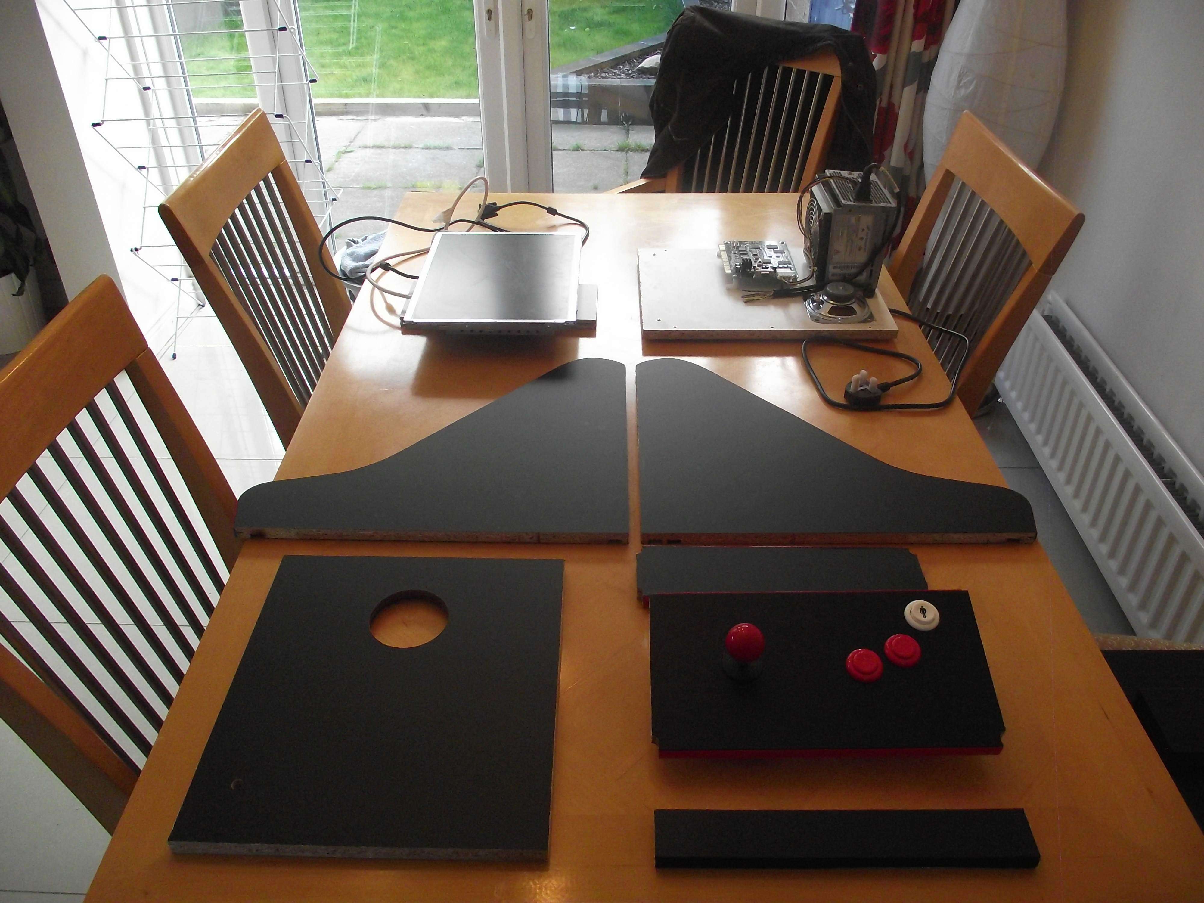
Once I got home I then marked it out with my template and prepared to cut out the pieces.
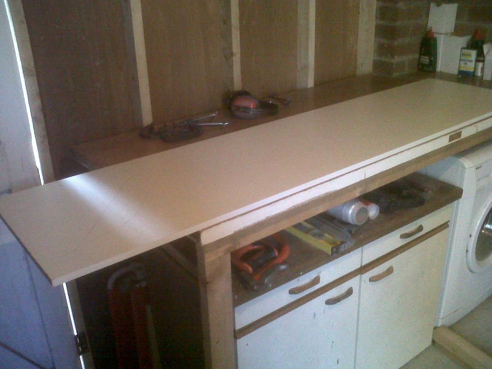
Once the first piece was cut I then used it as a template for my router. This enabled me to cut out the second side and end up with a matching pair.
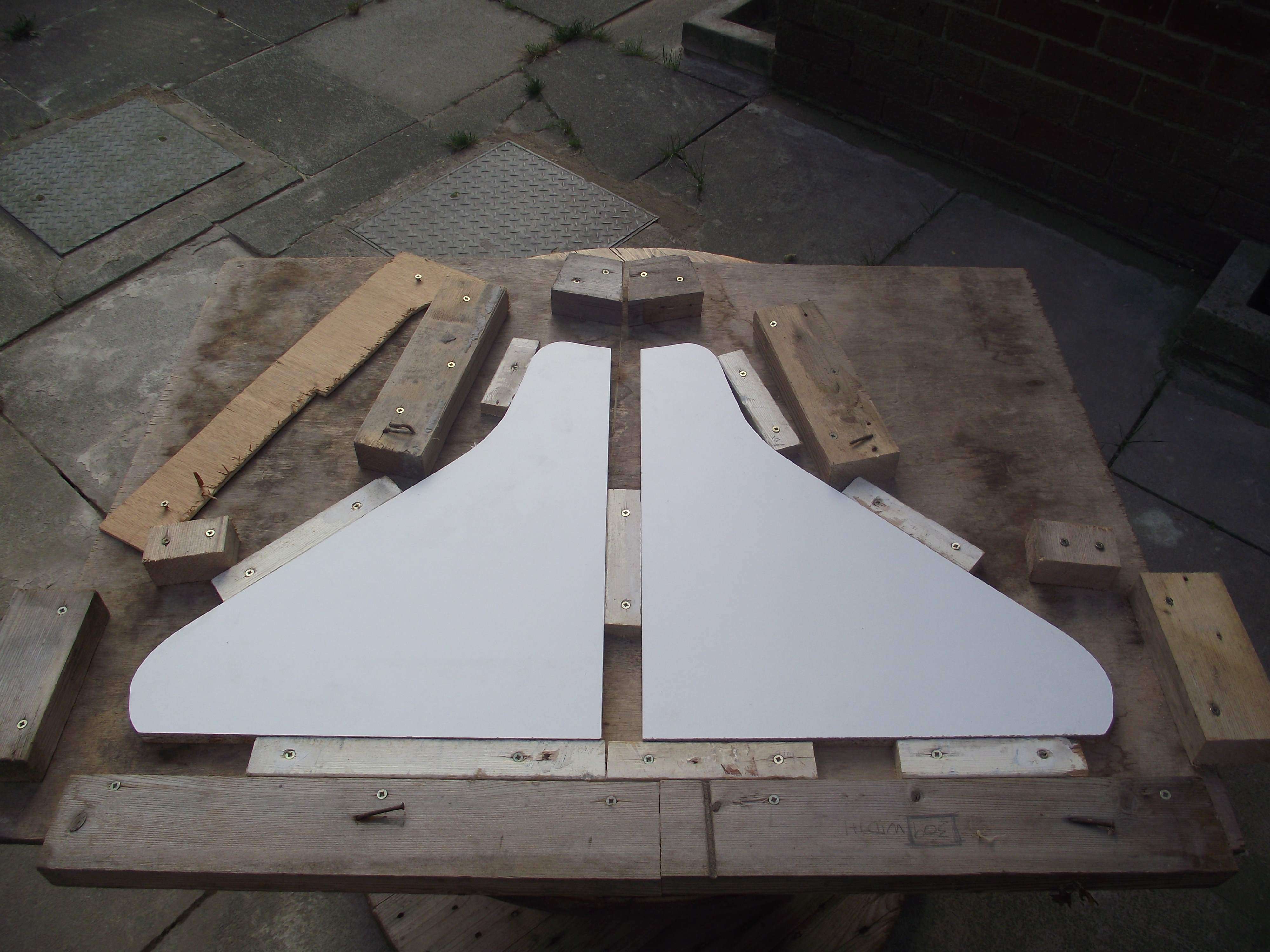
Once I had a match I then made a jig to hold my pieces.
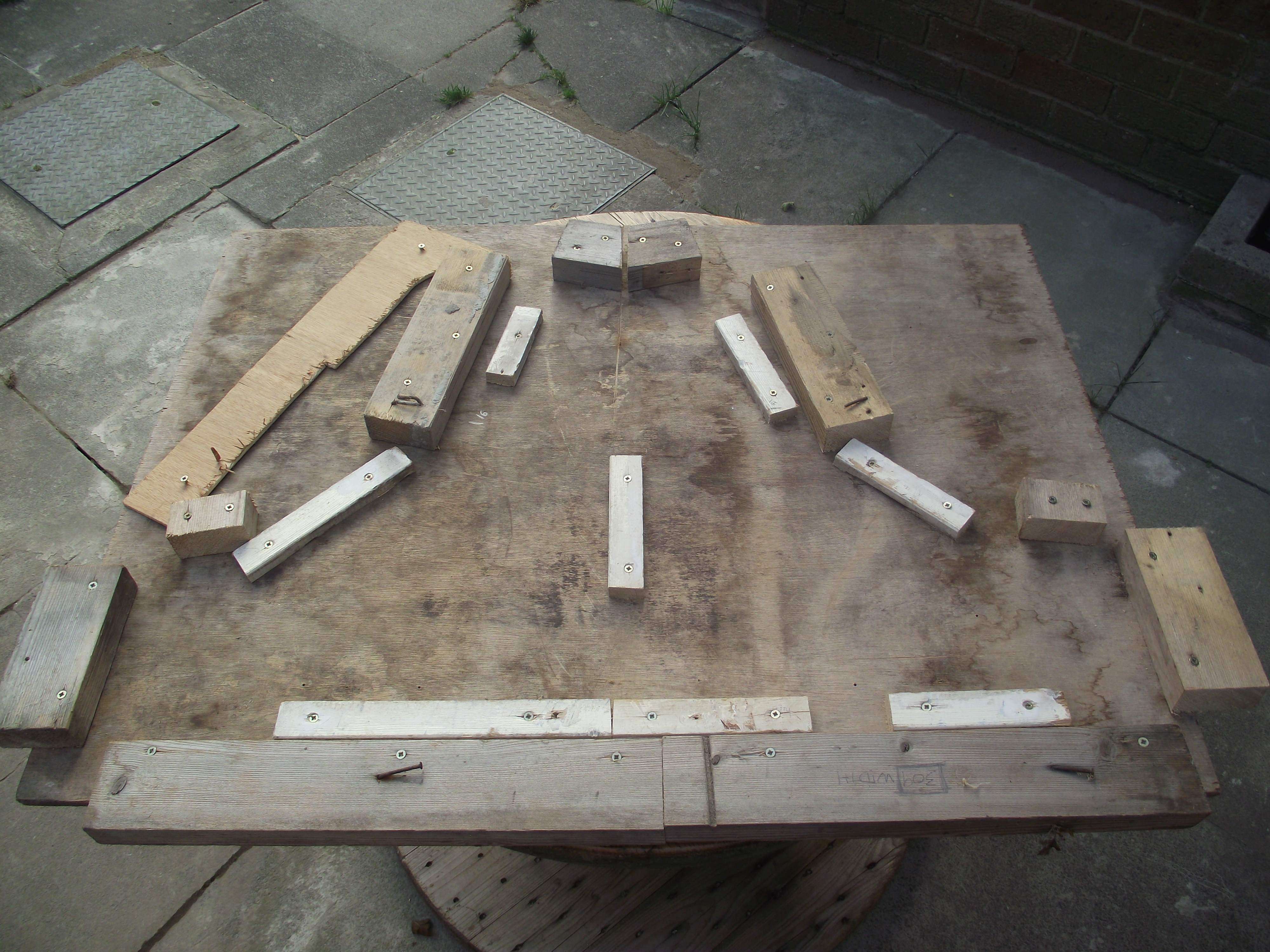
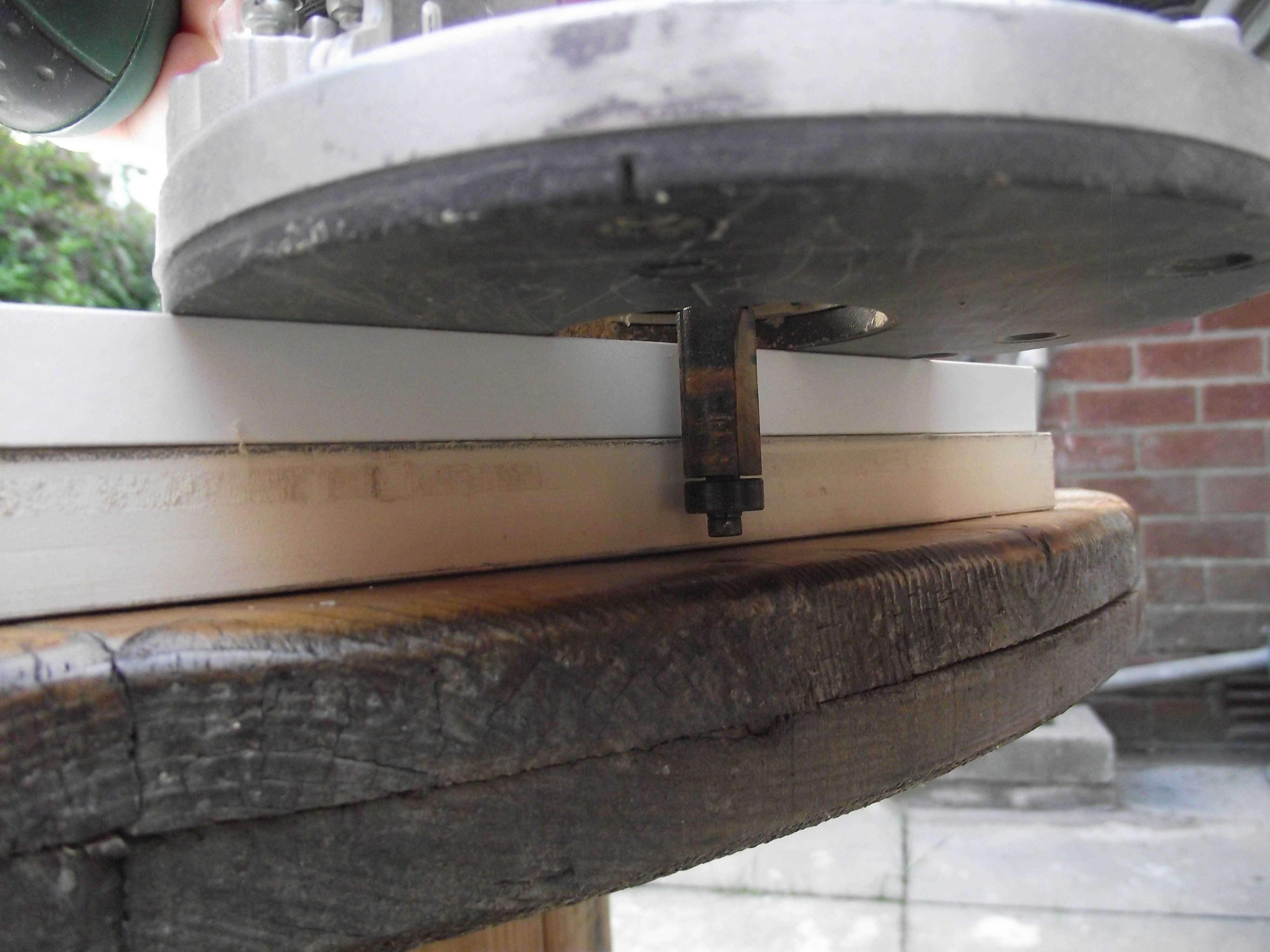
This was made from scrap wood I had lying about. From looking at other builds I noticed the norm was to glue/ screw blocks of wood to the inside and then affix the panels to this. I tried this on my other builds but felt it was cumbersome to get the two sides to line up and a lot of measuring was required. It also meant buying screws that were short and would not protrude out the side of the machine.
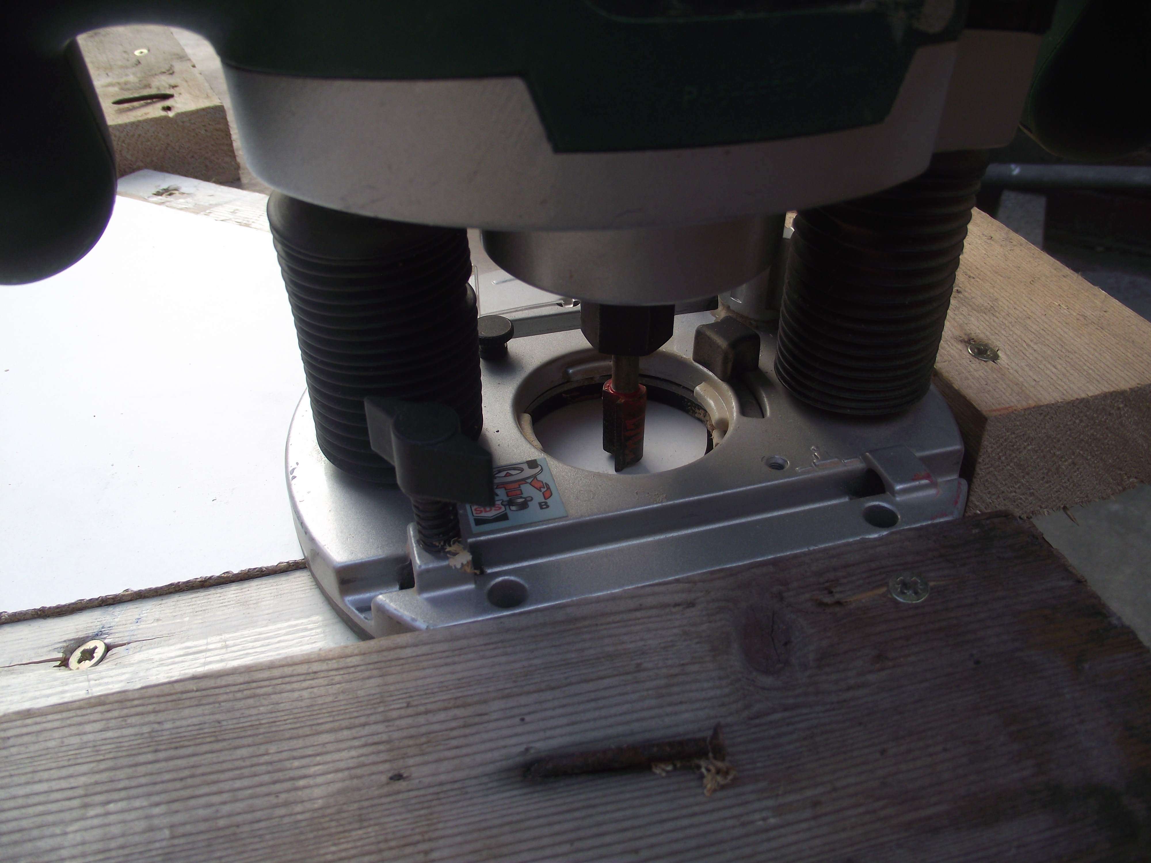
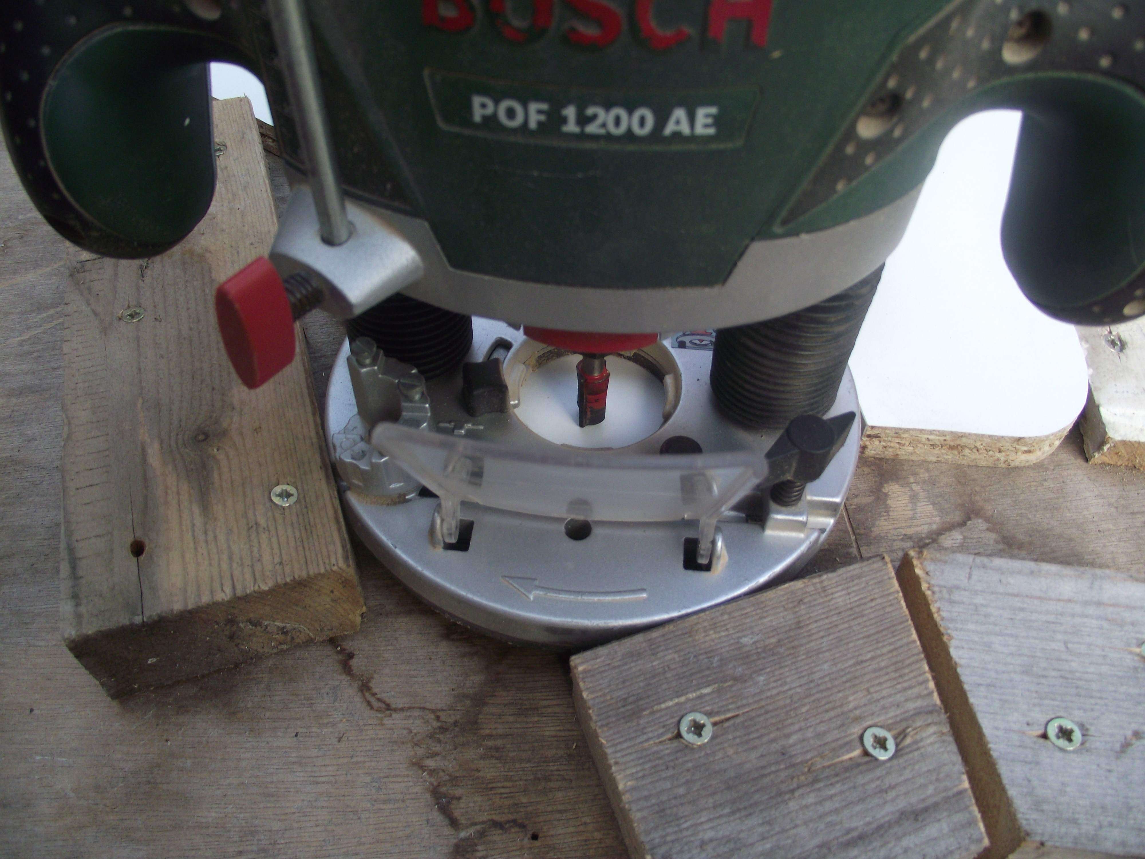
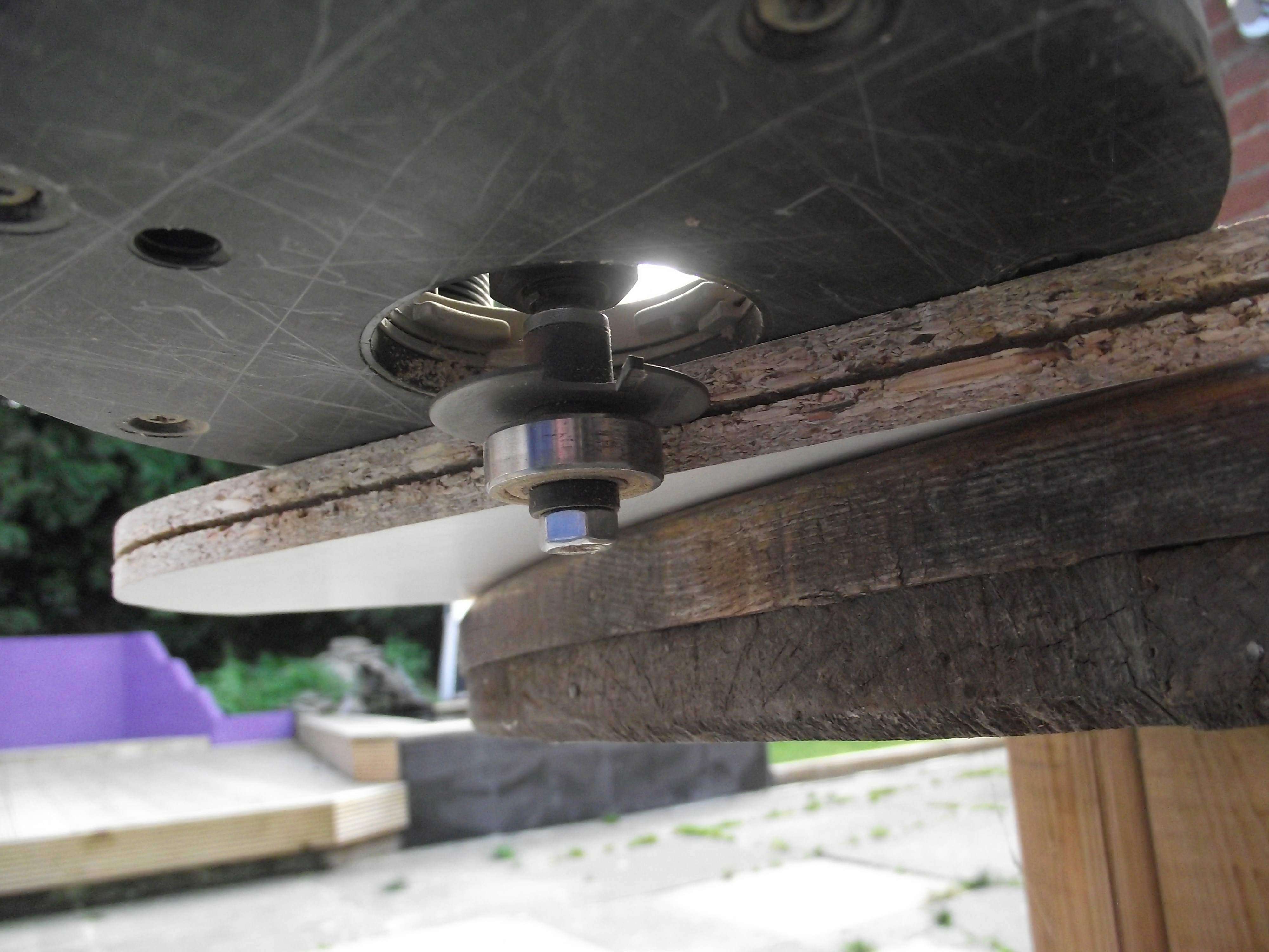
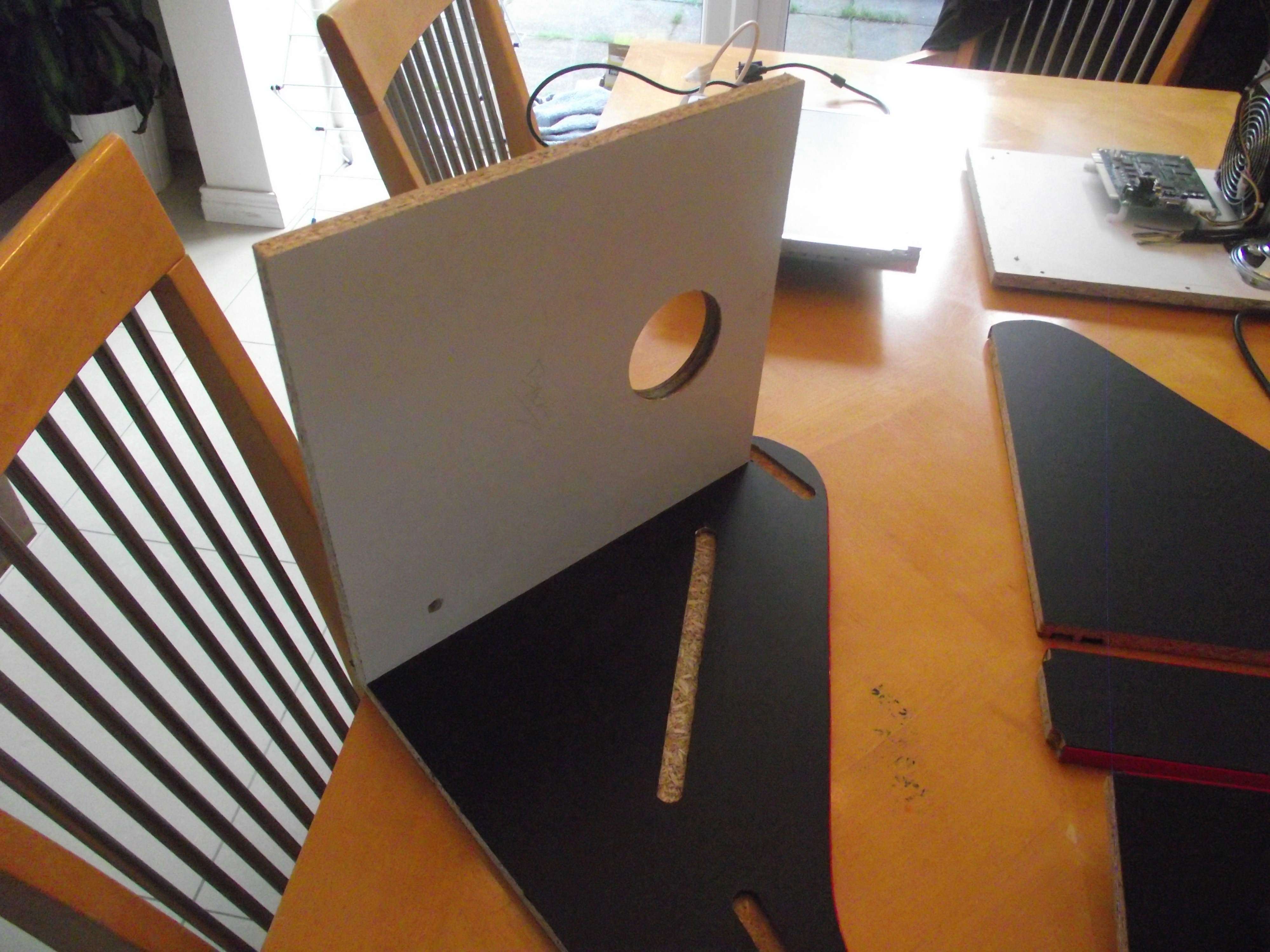
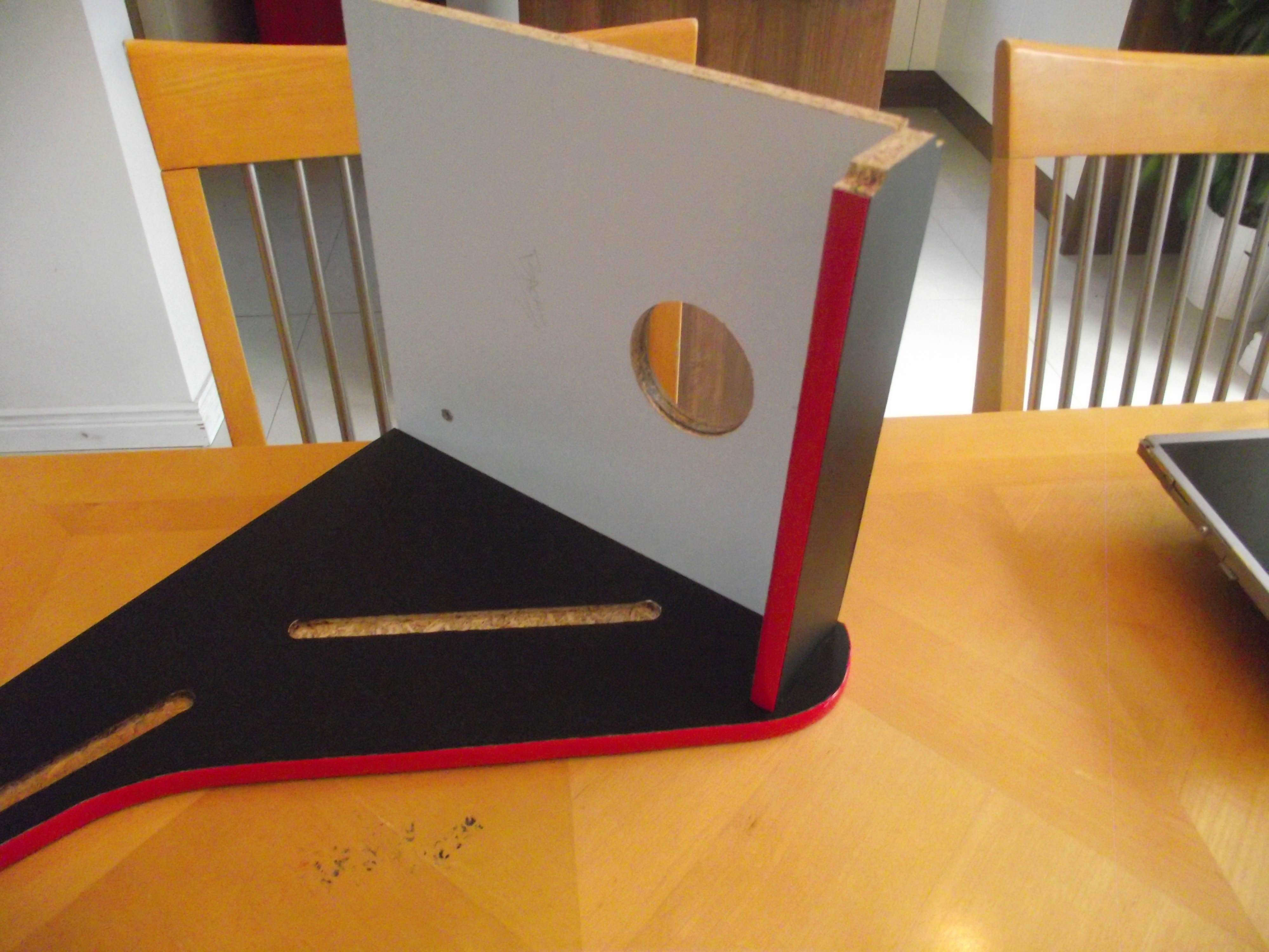
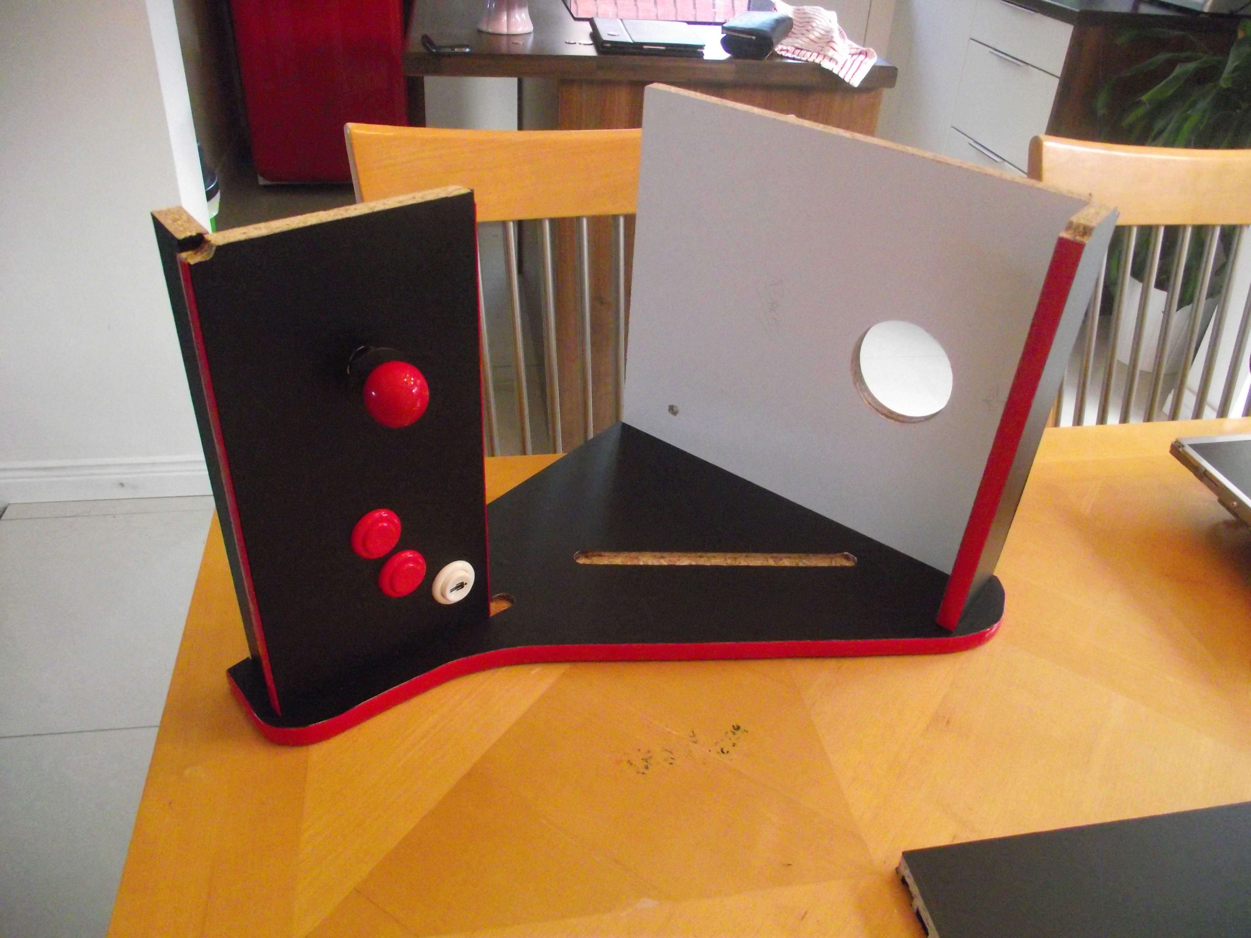
I had a eureka moment. I purchased a 15mm router bit and began trying to figure out how I could cut a 15mm grove on the side panels to create a slot. I came up with the router jig. As you can see in the pics, the edge of my router follows a piece of wood of which creates a perfect 15mm grove of which other panels slot into.
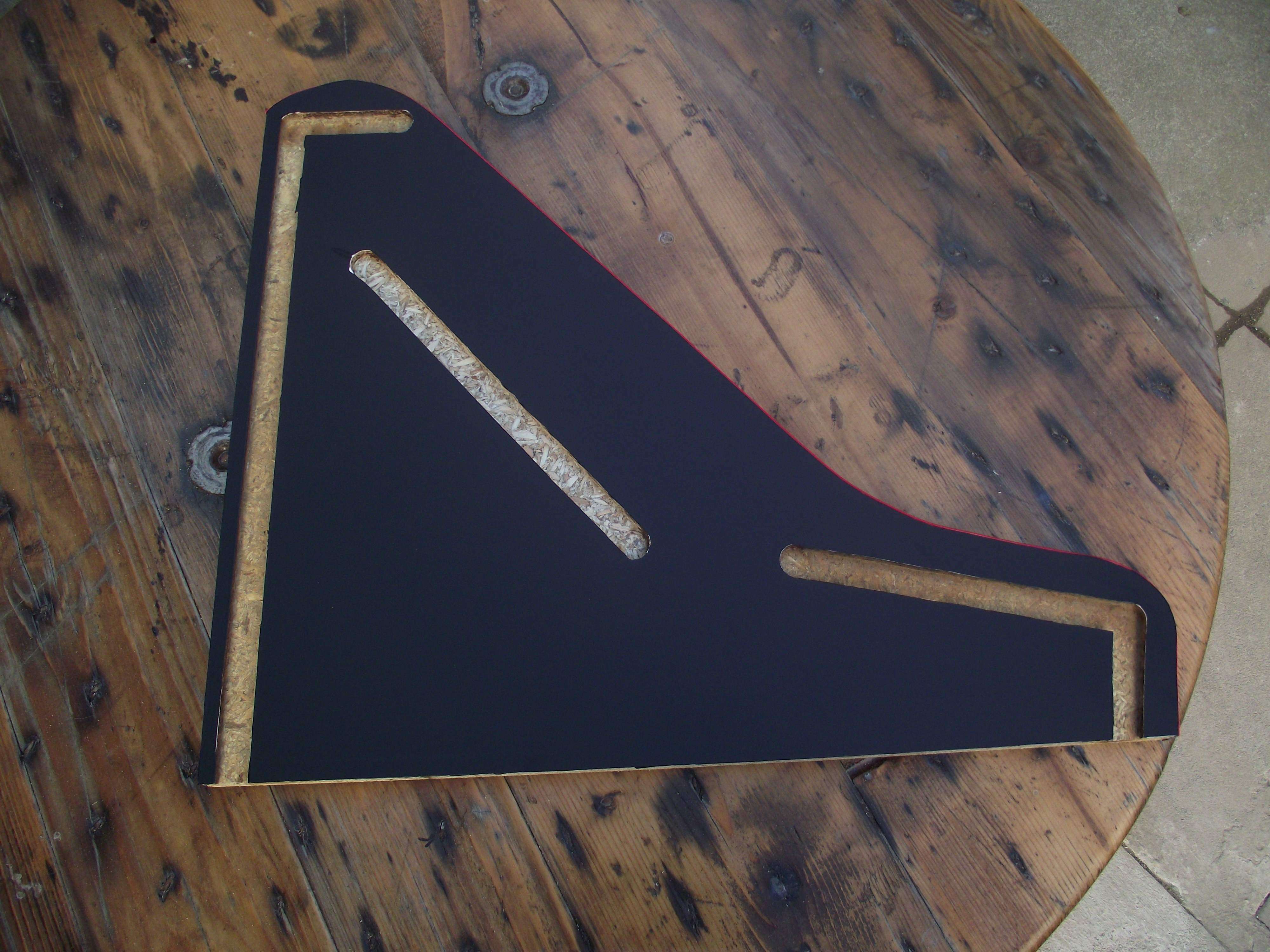
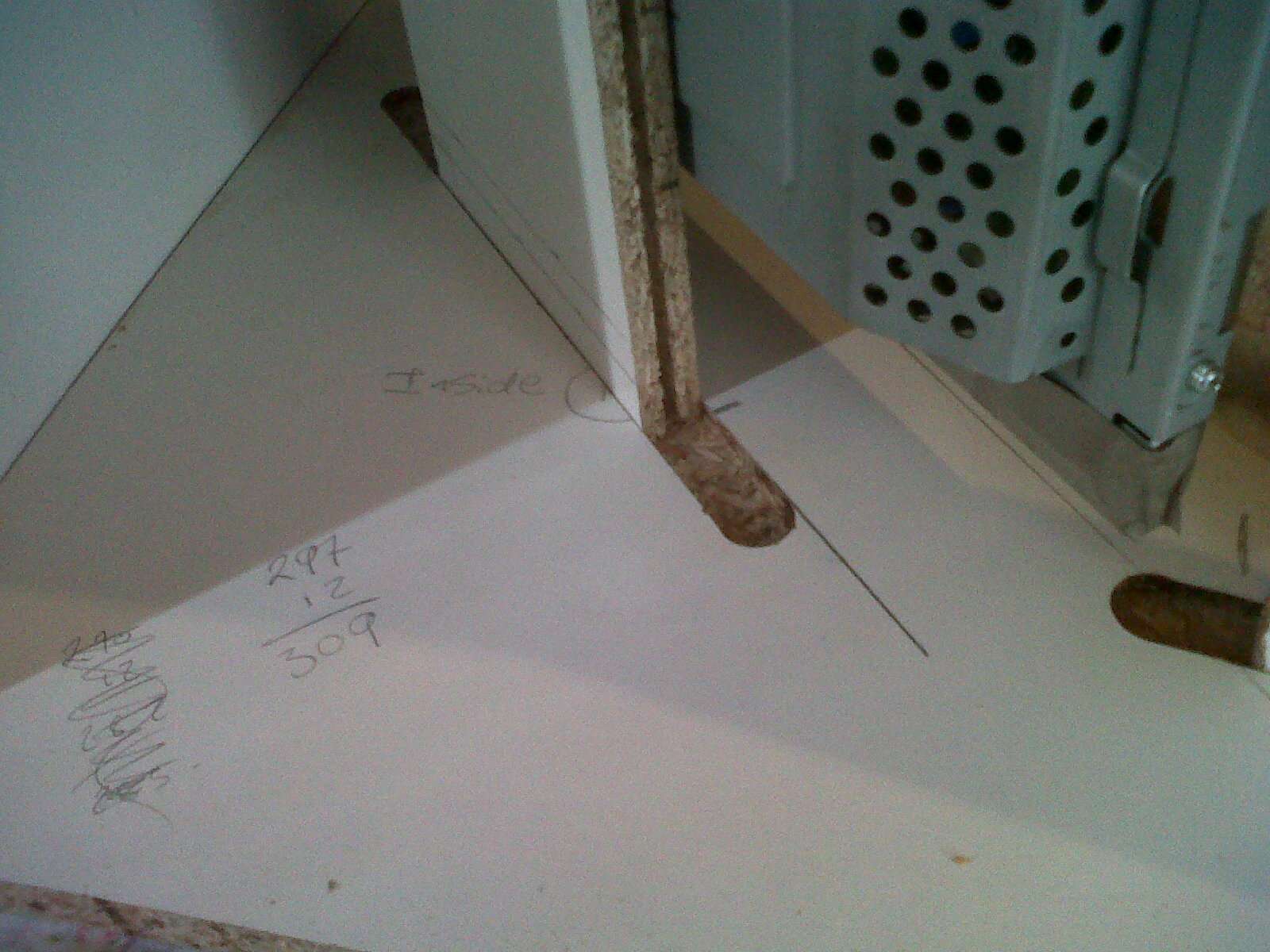
With the panels routed I then moved on with the build. The remaining panels such as the cp, the top and the kickplate were measured to fit the groove. I cut the remaining wood into a 312mm wide strip ( 6mm for the groove, 300mm for the screen area, and 6mm for the other groove). The reason for the 300mm width is because a piece of A3 sized Perspex / acrylic is roughly 298mm wide) no cutting required = efficient build.
Once I had my 312mm strip I then cut it into the relevant lengths for the cp, kickplate etc.
I then routed my t-molding slot.
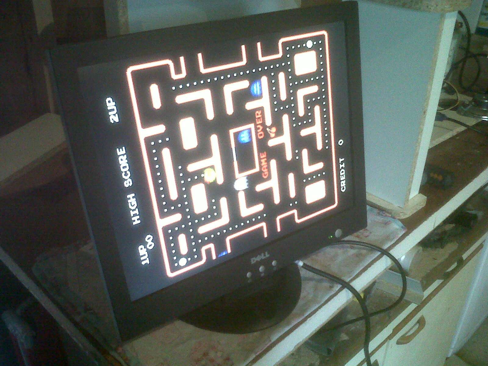
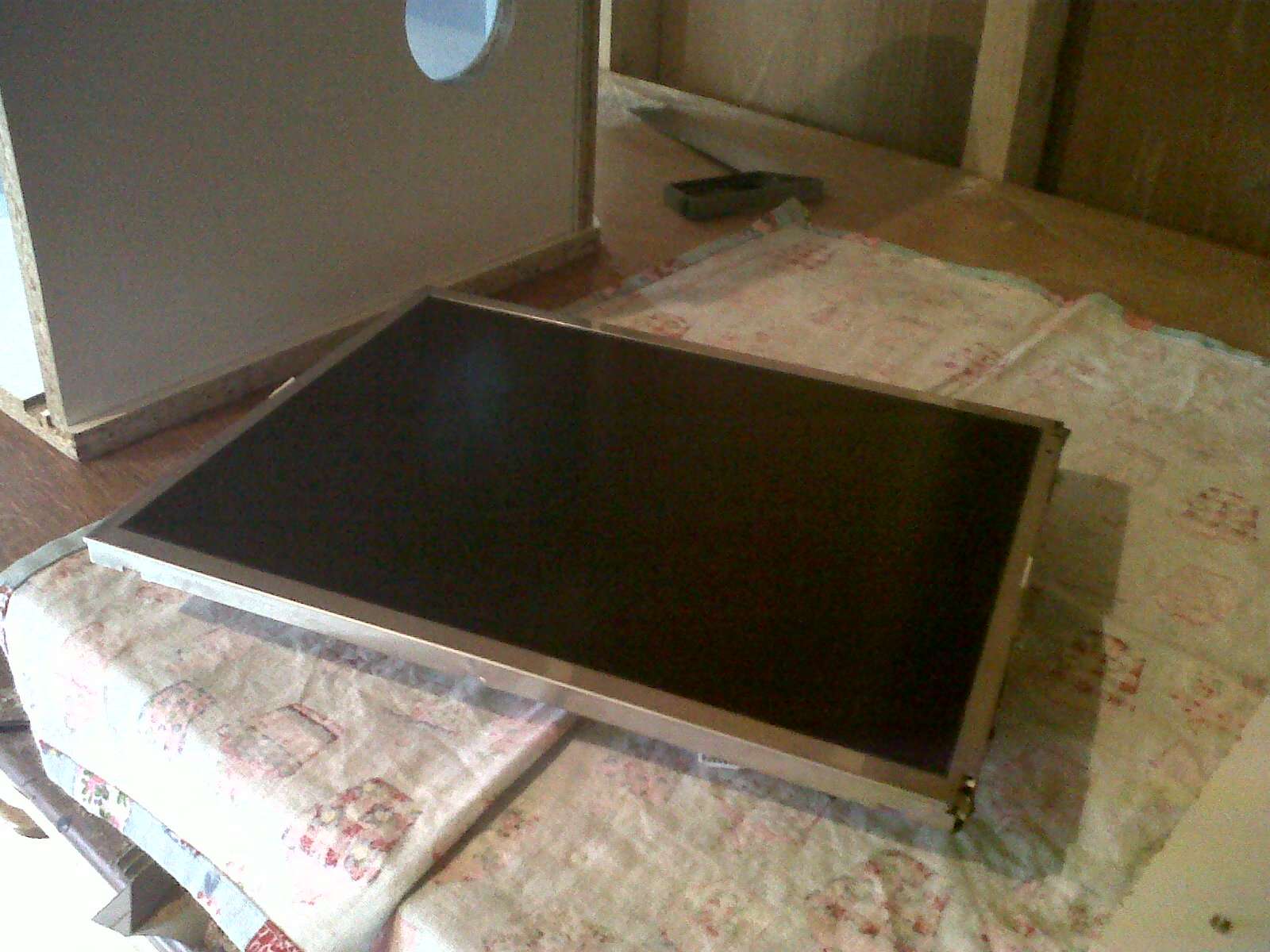
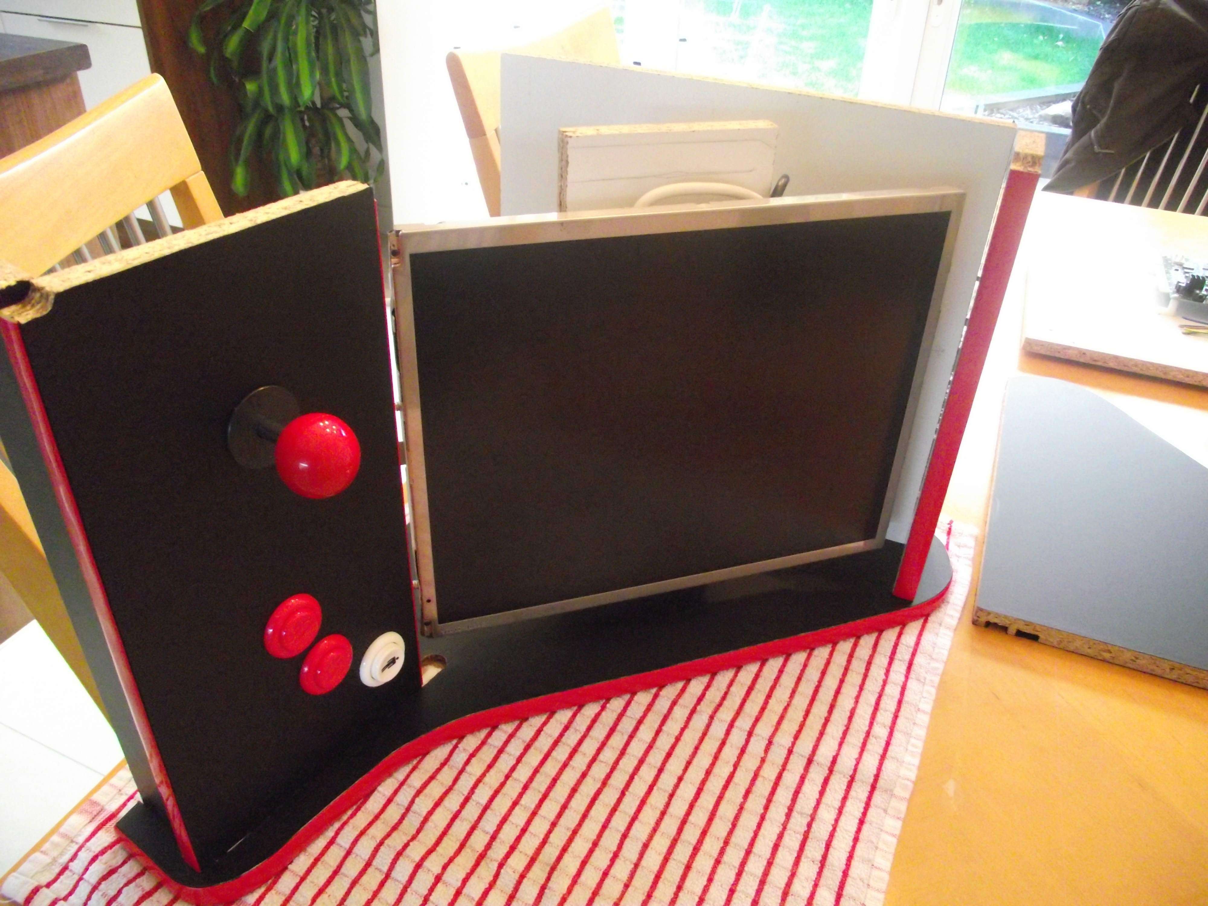
Once this was complete I turned my attention to the screen. It is a standard dell 15inch job, ebay special or what have you. I decased it and then grabbed a piece of leftover 15mm wood. I marked out the four VESA mount holes and a cheap mount was made. I then made several measurements to determine where the screen should be mounted. I then routed the groove. The extra length in the groove allowed me to slide the screen up and down until it was in the correct position.

I then wrapped the entire project in vinyl. I did this to save on having to paint the project.
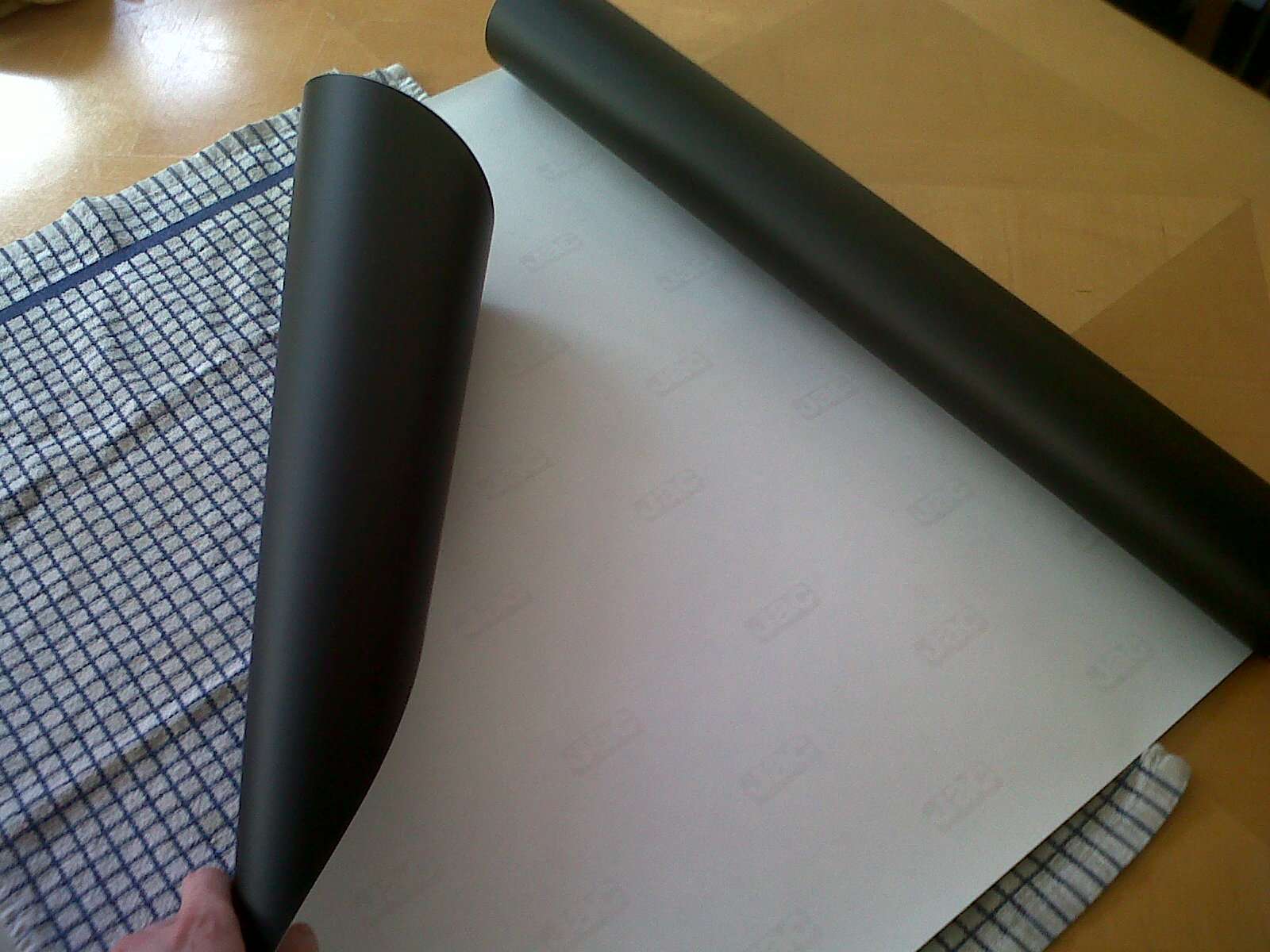
Once wrapped I then added the t-molding and assembled the machine. This involved no screws and only a small amount of wood glue. The 15mm slot is enough to hold the machine together but some glue was added for reassurance.
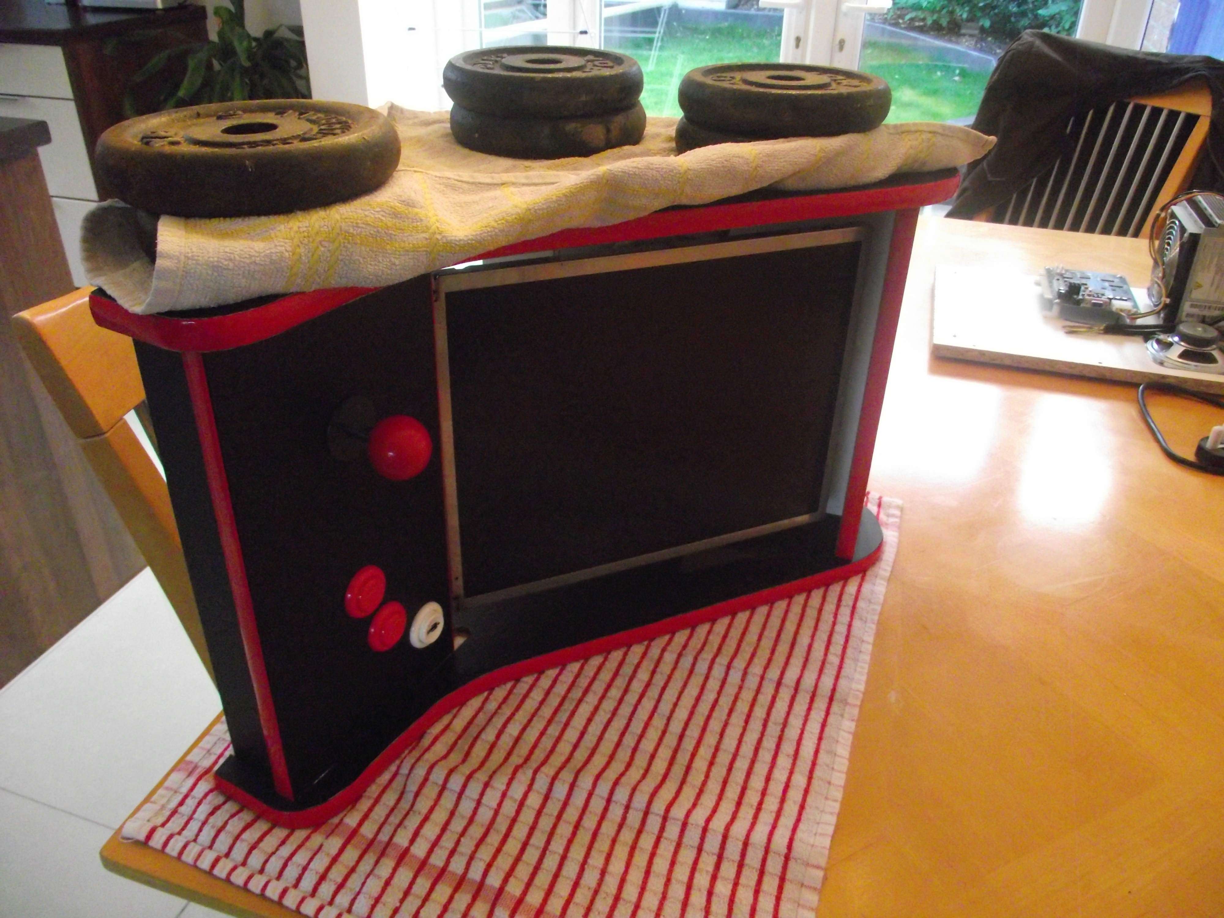
With my trusty weights added the machine was left to dry.
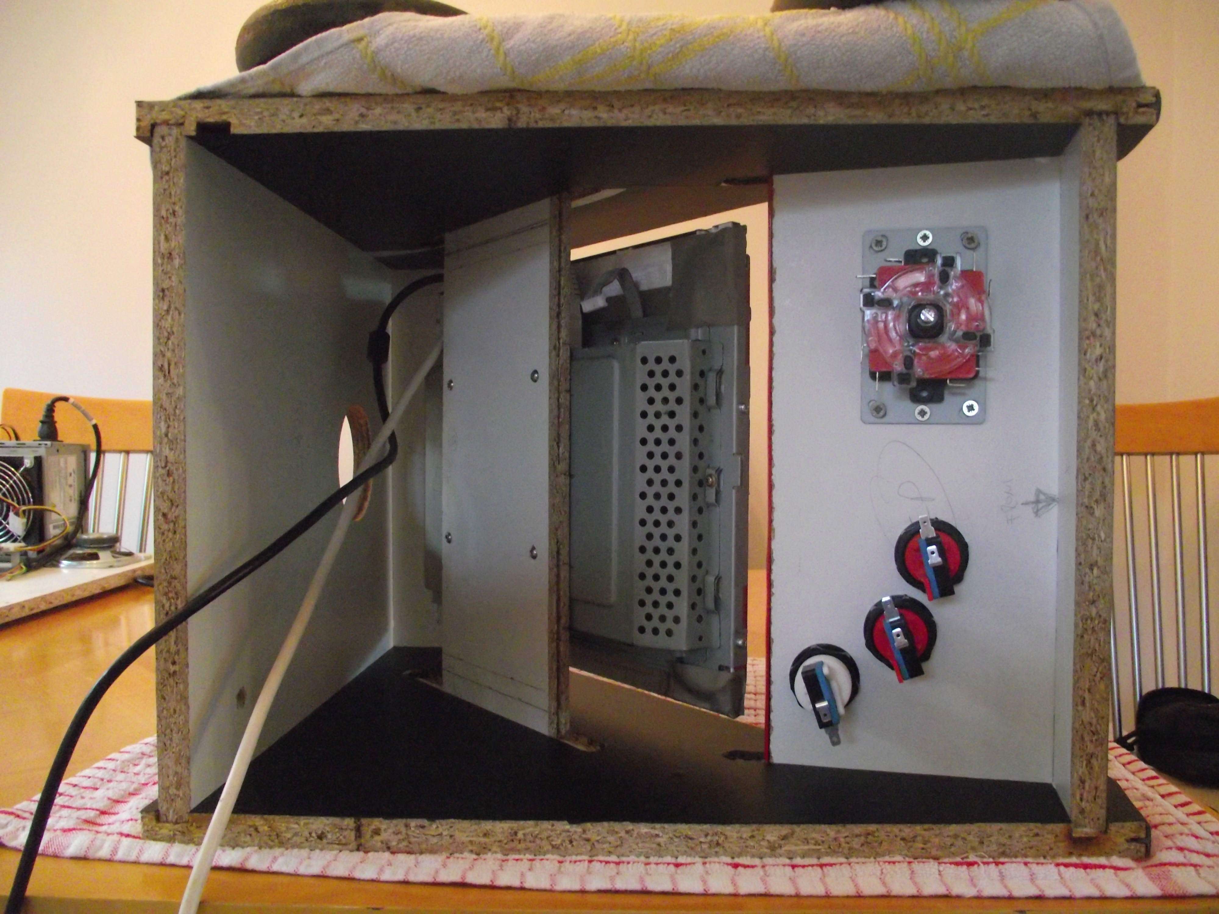
Stay tuned for my next installment,Using friction to fit the bezel, modifying a pc power supply and wiring a 60in1 board with variable sound control


 Home
Home Help
Help Search
 Login
Login Register

 Send this topic
 Print
Print Topic: Efficient bartop build - loads more pics added! (Read 8422 times)


