Hi, long time listener, first time caller. Well, this is a poor attempt at documenting my less than smooth road to build my very own arcade cabinet. This is my first post on these forums, so it may take a bit to get the pictures done properly and to communicate my steps with some clarity.
Sooo, what was my first step? Making sure that the wife was okay with an arcade cabinet in the extra bedroom of course.

After that I read a lot and studied different cabinet designs. One thing I was certain of from the beginning was that I wanted a rotating monitor. I had an old LCD Samsung 22 monitor that had quit working, a victim of the capacitor plague. So for about $5 worth of capacitors, I got it working again. I also had an old computer that I wasn't using. I settled on a Centipede cabinet design, because I felt it was a good generic arcade cabinet design.
Cabinet design? Check. Computer? Check. Monitor to rotate? Check.
The first thing I needed to do was to get the monitor rotating mechanism working. I decided to go with Psychotech's approach, thanks much Psychotech.

. So I went to Home Depot and got some 1x4s, some mdf and a guage set that you attach to a jig saw to make large circles. I found a small split rim wheel at Tractor Supply for around $10 that would accommodate 1/2 all-thread for an axle. I forget how big the mdf was, I think it was 2ft.x4ft.
First I cut an adapter plate out of 1x6 to go between the monitor and an 18 circle of mdf. I filed the adapter plate to fit perfectly on the back of the monitor and drilled 4 holes for the monitor mounting screws. With the adapter plate in place on the back of the monitor, I used some string to mark the center of the monitor on the adapter plate by diagonally stretching it from corner to corner of the monitor. I then removed the adapter plate and drilled a 1 1/4 hole at my mark to accommodate the nut that was going to be attached to the all-thread.
Next, I cut the 18 circle out of mdf using my jig saw and newly purchased guides. I had gotten the mdf cut into a 18 square when I was at
Home Depot, so it was just a matter of marking the center with diagonal lines from corner to corner and attaching the guide. After the circle was cut I placed the adapter plate onto it, and marked the monitor mounting holes on the mdf circle and drilled them out. I then drilled a 1/2 hole in the center of the mdf circle. I took my all-thread, put some loc-tite thread locker on the end, screwed the nut on until it was flush with the end and slipped a fender washer over the other end. I then pushed it through my mdf circle, slipped another fender washer over the end followed by another nut. More loc-tite on the threads where the nut would rest when tightened, and I tightened it securely, sandwiching the mdf circle between the nuts. I then placed my adapter plate back on the back of my monitor, and using 4 m4x50mm bolts and lock washers, I attached the mdf circle to the back of the monitor, sandwiching the adapter plate between the monitor and the mdf circle. I now had a monitor with an axle.

I wanted the monitor to be tilted slightly back, by about 5 degrees. I wanted the assembly to be about 25 inches high, and using some trig formulas I found on the net, I was able to figure out the lengths and placement of the 1x2s to achieve the tilt that I wanted.
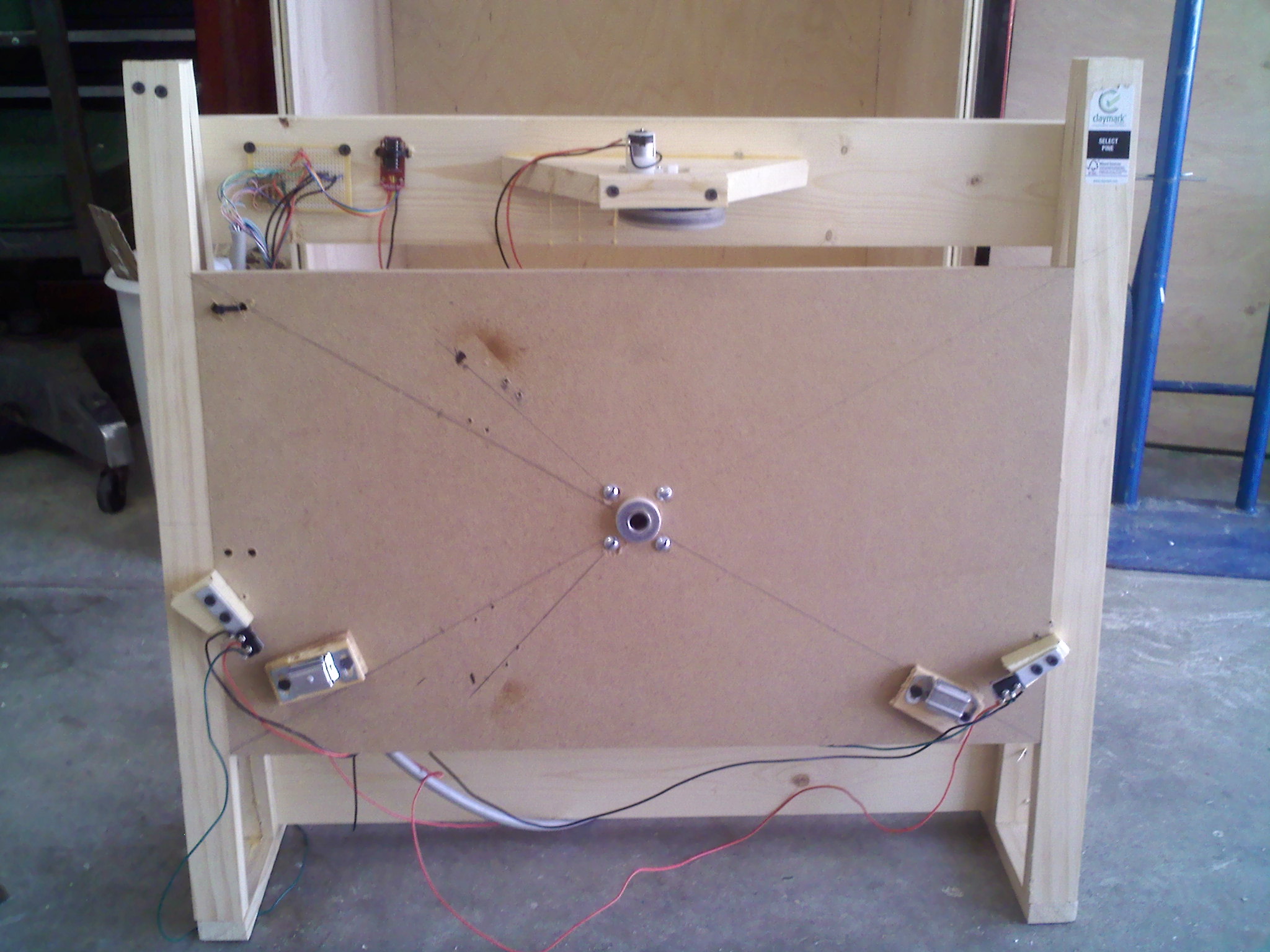
Sorry, I don't remember the exact measurements to achieve the tilt. Anyways, I screwed the two brackets to a piece of mdf about 14 wide and 24 1/8 wide ( I knew my cabinet would be 27 1/8 wide on the inside). Now I had my base to mount my bearing assembly in. I took apart the wheel I had purchased from Tractor Supply. The wheel had 4 bolts through the rim to keep the two halves of the rim together. The hub was slightly smaller than 1 1/4 diameter, so I drilled an 1 1/4 hole in the center of my mdf base. I placed the hub into my base and drilled 4 more holes through the rim bolt holes, and bolted the hub in place on the base. Due to the way the hub was made, when I placed the 1/2 all-thread through the center and tightened the nuts down, they contacted the inner bearing race of the hub. This allowed me to adjust the friction on the turning mechanism by pre-loading the bearings instead of using the 4 casters as Psychotech did.
I took some small pieces of aluminum stock and made some L shaped brackets and attached them to the back of the mdf circle. These brackets would be the contacts for the micro switches I would be mounting on the base. I put the monitor assembly into the base and marked where my micro switches would need to be mounted. Disassembled it and mounted the switches. After much trial and error, I figured out that I needed some physical stops for the rotating mechanism. So I attached a couple of 1x2s to the back of the mdf circle to attach the little metal plates of cabinet catches. Then I mounted the cabinet catches onto the base. I was now ready for the electronics part of mechanism....and a beer.
I ordered the parts listed by Weisshaupt from Solarbotics, thanks Weisshaupt.
The following is an excerpt from
this post.
GM3 motor (easier to mount than the GM2)
http://www.solarbotics.com/products/gm3/The Regular Motor 2 upgrade
http://www.solarbotics.com/products/rm2/The mounting Bracket
http://www.solarbotics.com/products/gmb39/A wheel
http://www.solarbotics.com/products/gmpw/A Extra Grip Tread (it is a friction drive after all- the more tire that meets the road)
http://www.solarbotics.com/products/gmtt/And then for the Electronics you need:
A Chip socket:
http://www.solarbotics.com/products/dc-16_pin/The secret Motor Driver Kit
http://www.solarbotics.com/products/k_smd/I had to get the GM2 motor because they were out of GM3.
The parts have to be assembled and soldered. Flux and a steady hand are lifesavers. I used a soldering iron to keep the heat low. Also a solder wick can be helpful, which is really just a bit of unbraided wire.
I mounted the motor and controller onto one of the cross pieces of the base... 3 times. The first time I mounted it, I made and adapter out of 1x4 and attached it to the base.
This was my first attempt.
What I didn't understand at the time was that wood, unlike mdf and plywood, is NOT dimensionally stable , it moves

. What I finally ended up doing was creating a floating bracket for the motor. I used some 3/8 metal stock, bent it into a L and drilled a hole in the middle and a hole on the end. I put a spring I bought from Tractor Supply through the hole on the end. I then mounted the bracket to the adapter I had used to mount the motor the first time, by drilling a hole through the adapter and running a bolt through the center hole of the bracket with a lock-nut. I then attached the motor to the vertical part of the L with a hose clamp. Hopefully this picture will get the idea across a lot better than I worded it.
This is an abstract of the final solution.


The nice part about this mechanism is, it not only makes up for the wood movement, but it also compensates for run-out of the mdf circle and absorbs some of the shock when the mechanism hits the stops. I also glued some 600 wet/dry sandpaper with super 77 trim adhesive to the back of the circle where the wheel of the motor contacts it, for added friction.
Now that all the parts were in place, it was time for computer programming part and another beer. All I can say is thank God for Da Old Man. Using his
program and wiring diagrams I was able to get my monitor rotating by using the computer. Unfortunately it wasn't the old computer I was using. That computer decided to give up the ghost right about the time I was going to hook it up to motor controller. Sigh, so about $400 later I had a computer hooked up the motor controller via the parallel port. In my infinite wisdom, I decided to use an extra copy of Windows 7 64 bit I had laying around. Well, Da Old Man's program was written for a 32 bit XP system, and the program worked well, except that it turned my monitor at full speed. So I e-mailed Da Old Man to ask him if he had any ideas on how I could fix it. He got right back to me with some ideas and things to try. This was a pleasant surprise, I didn't really expect support for the program, it was free, after all. But with Da Old Man's help, I got the mechanism running perfectly. I really can't say enough good things about this guy, he stayed in touch with me until I got the thing running perfectly which took more than a few tries. Big time thanks to Da Old Man. His assistance is a big part on why I am doing this write up, and trying to give back to community some of what I've taken.
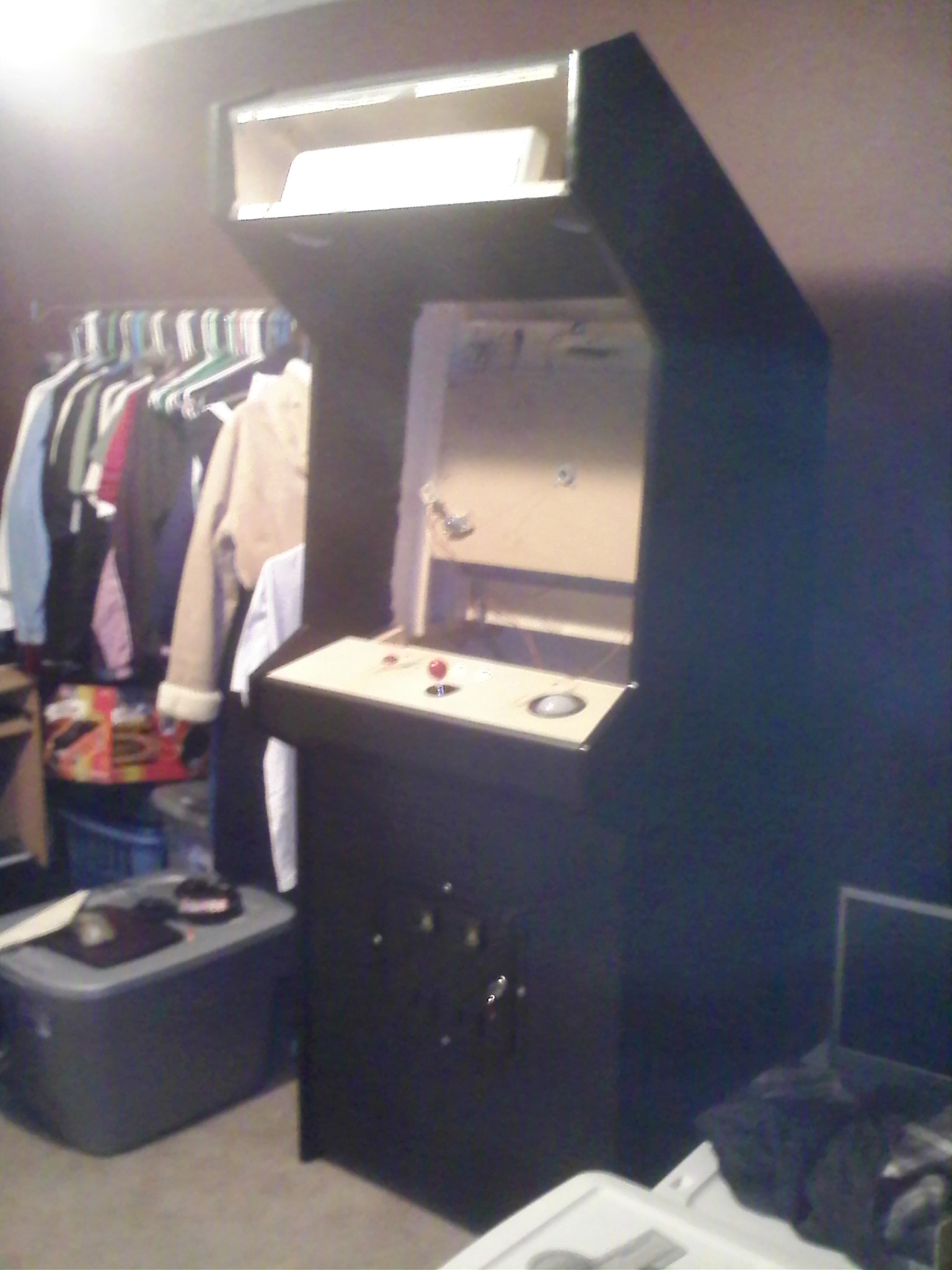
Well, now that the monitor is working, time for the cabinet. I got the designs for the cabinet off of
http://www.jakobud.com/plan-list.php . I had to use some trig formulas to figure out the angles. I also had to make some adjustments to accommodate the monitor and raise the control panel for better comfort. I used Birch plywood because it was my understanding that it would handle paint the best.
Building the cabinet itself wasn't too bad. I've never been a wood worker except for wood shop about 40 years ago. So first, I had to build a workbench, then saw horses and buy a router. I had a cheap Skil saw and a Black & Decker jig saw. I used a
guide I bought from Home Depot to make straight cuts with the circular saw, which worked well on the short cuts, but had too much flex for the 8 ft. cuts. I used drywall screws to assemble everything, so if I needed to, I could take it apart again, which I did, several times. So since putting a box together is pretty straightforward, I'll just touch the lessons I learned.
When I cut out the sides, I stacked the plywood to cut out both sides at once, which worked pretty well until I tried to use the jig saw to make the inside cuts. The thickness of the cut and my inexperience with a jig saw caused the blade to deflect, severely. Fortunately I was able to go back over the cut with the router to straighten up. After that, I used a router with a straight cut bit and a straight-edge to make the cuts I couldn't make with the circular saw. Also, a cheap circular saw does not cut bevels well, at least mine didn't. So I had to buy a slightly better Craftsman circular saw which got the job done.
I got my t-molding and the router bit to cut the slot from Groovy Game Gear
http://groovygamegear.com/webstore/. I didn't really know how to use a router properly, so when I tried to cut the slot for the t-molding, I tried to do it in one pass. I burned the wood cutting the slot, to the point of filling my garage with smoke. After that I made several shallow passes with the router and that worked MUCH better. Also when I tried to cut the hole for the trackball with the jig saw, I had problems with blade deflection again, so I just made a jig for the router to cut the rest of the holes I needed, speaker holes, fan holes etc. A word of caution about the router, make sure you cutting in the right direction, other wise it tries to take off on it's own. I found this out the hard way and almost ruined the hole I was cutting for the coin door, not to mention scaring me half to death. Fortunately the coin door completely covered the gouge. After that experience I did a lot more reading about safety with wood working, I found these sites to be quite helpful
http://newtowoodworking.com/ and
http://thewoodwhisperer.com/.

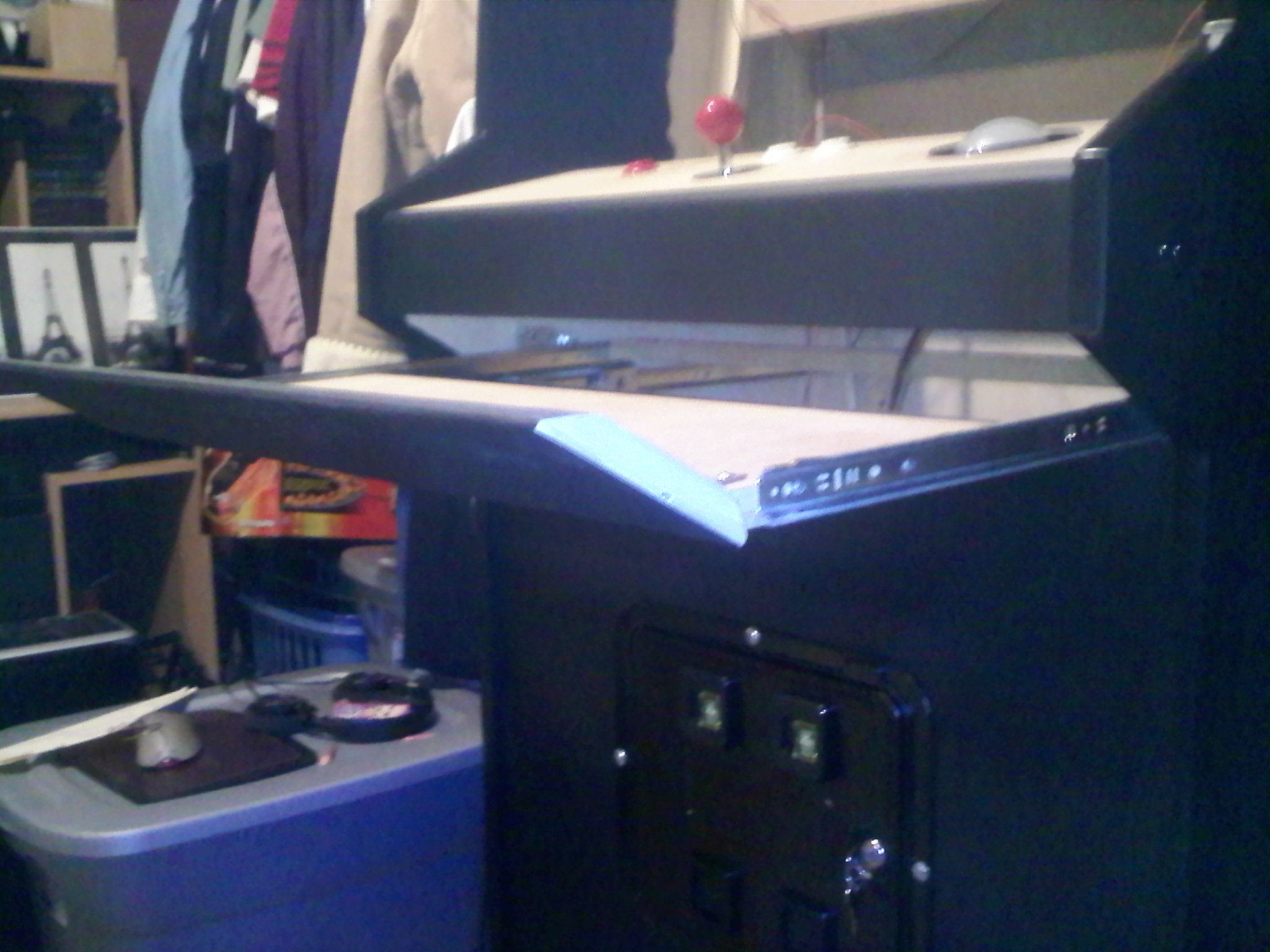
A couple of other things I should mention about the cabinet design, first: I knew from the beginning I was going to use either swappable or modular control panels. It's just me and my wife since the kids are grown, so I was only designing a two player machine. Since it was only going to be a two player machine, I decided to go with swappable control panels, besides, it just doesn't feel like defender without the proper button layout. Second: the boss said it needed to have a drawer for the mouse and keyboard, so I put a drawer in for a mouse and keyboard.
To make the swappable control panels, I used a kind of french cleat design along with a draw hasp to hold the panel securely in place. I can get carried away while playing and I get pretty rough on the controls, so using Velcro or a peg and hole system just wasn't going to work very well. So far I have 5 different control panels and plan to make a few more. I used network cable and RJ45 plugs to wire up the buttons, joysticks(4-way) and the LEDs. I also mounted a couple of USB hubs for the U360 joysticks, trackball and spinner. Each control has it's dedicated USB plug spot on the hub, if you start mixing up the plugs things don't work as well.
Control panel french cleat system


Here is the drawer
I painted the whole cabinet with a flat black interior acrylic wall paint. I used a high density foam roller that worked pretty well and left a little bit of orange peal, but not a lot. I was going to spray paint it, but due to a lot of windy days, my extremely poor painting skills, and strong suggestions from the missus, I decided to just use house paint with a roller. I used black shelf paper to cover the control panels, I just felt like it would be more durable and easier to replace than paint. I used black foam core for the screen matting, I attached it with 3M mounting tape. I used plexiglass for the front glass. Plexiglass is really fragile, I dropped the first piece about 4 inches by accident and it broke a corner off and severely scuffed it where it hit the chair on the way down.
As a side note, when I tried to install the circle adapter plates to the bottom of the U360 joysticks, a couple of the pillars weren't machined quite enough and snapped off in the base of the joystick, so you've got to be really careful with them. Andy at Ultimarc graciously replaced the base and pillars for me. It took about a week to get the replacements.
Also if you do get the U360 joysticks I highly recommend that you also purchase the the adapter plates. The U360 joysticks do not have switches in them, they instead use a magnetic field to monitor the position of the joystick and without the adapter plates the joystick can move out of the sensor range.
That being said, I think the U360 joysticks are really cool and if I have need of more 8 way joysticks, I'll probably purchase them again. They are completely quiet and totally programmable and customizable. Really, what more could you ask of a joystick.
I have since learned that the pillars are now manufactured from a more resilient aluminum and machined to more stringent specifications. Also there were some design changes to correct the going out of sensor range, so it's my understanding that buying the adapter plates is more of an option than a requirement.
I would like to mention that the items that I ordered from Ultimarc were received in about 3 days, which was really quick considering I'm in the States and Ultimarc is in the UK (I got my stuff from Ultimarc before I got my stuff from Groovy Game Gear, even though they were ordered on the same day).
Coin door and marquee molding was ordered from Happs
http://www.happcontrols.com/. Buttons, spinner, led controller and 4-way joysticks was ordered from Groovy Game Gear
http://groovygamegear.com/webstore/. Trackball, led kit, and 8 way joysticks were ordered from Ultimarc
http://www.ultimarc.com/. Atari volcano buttons were ordered from Ram Controls
http://www.ram-controls.com/.
I think that's everything. Hopefully whatever I didn't explain was self-explanatory. Thanks to Psychotech, Weisshaupt, Cornchip, Da Old Man, Mame, Mala and countless others that enabled me to bring a dream to life.


 Home
Home Help
Help Search
 Login
Login Register

 Send this topic
 Print
Print Topic: Rotating monitor project (long) (Read 8647 times)


